Coupling is a mechanical device used to couple the shaft for transmission of power from driving shaft to another driving shaft. Assuming design torque to be 15 times the rated torque.

Flange Coupling Eg Using Autocad Flange Coupling Assembly Drawing Step By Step Process Youtube
Assembly of muff coupling is shown in Figure 161.

. In this types of shaft coupling the flange and hub are separately assembled together instead of a single part as flange coupling. Here is the simple and easiest method for drawing FLANGE COUPLING ASSEMBLY in AutoCAD software. Cad 3D Flange Drawings Sorted by.
Training Video For professional Designer. Box 1069 Santa Maria CA. It is simple to design and manufacture but.
Flange coupling is a type of Coupling used between rotating shafts that consists of flanges one of which is fixed at the end of each shaft the two flanges being bolted together with bolts fitted circumferentialy to complete. Flange Coupling Unprotected Creo part Design And Assembly. This capability is a result of an ongoing partnership with Trace Parts an online library of parametric components for 2D3D CAD assemblies.
Consider a flange coupling as shown in Fig. Using CAD Firstly we create constrained sketch with dimensions. It is required to design a rigid type of flange coupling to connect two design shafts.
On the basis of strength plain carbon steel is used for. So it is very easy to calculate all the dimensions in. Assemblies tailstock radial engine bush type flexible coupling oldham coupling universal coupling Flange Coupling swivel bearing Foot Step bearing socket and spigot joint Sleeve and cotter joint knuckle joint claw coupling gib.
Considering a standard motor with Power 375 kW and RPM 180. Part modelling Part design. Creo Part Design Assembly Learn In easy Way.
Autodesk_AutoCAD_2D_Blocks Download Full Package Software Inclusion Report. We are making a 3d design of flange coupling using CatiaV5 and analysing with Ansys18. It is a member of 78xx series of fixed linear voltage.
Gear couplings can transmit high torque because of the large size of the teeth. Is a modification of the rigid type of flange coupling. Due to their short design these curved-tooth flange couplings are particularly suitable for mounting to I.
Highly flexible flange couplings BoWex-ELASTIC. Viking Johnson design and manufacture of couplings flange adaptors pipe connections repair and flow control products and shouldered and expansion joints for international water and gas markets. Vaibhav Patel-September 25 2014.
Using CAD Firstly we create constrained sketch with dimensions. 2D Drawing FLEX 125 DXF 3D Drawing FLEX 60 STP 3D Drawing FLEX 125 STP Accessories - Brackets - Tubes hoses - Hose tube connectors - Reducers Reducer coupling - Extensions - Angles - Overview. The gear coupling is a modified version of the flange coupling.
Let d Diameter of shaft or inner diameter of hub D Outer diameter of hub d1 Nominal or outside diameter of bolt D1 Diameter of bolt circle n Number of bolts tf Thickness of flange τs τb and τk Allowable shear stress for shaft bolt and key material respectively. We have a 2d designed drawing with required dimensions and components for assembly. Following drawing shows the Protected type flanged coupling with proportions expressed in terms of.
Design specification of coupling. Sleeve a hollow cylinder is fitted on the ends of input and output shaft with the help of a sunk key. April 16th 2020.
The design o f pr otected type rigid flange coupling is as pe r standard design procedure which mainly co nsists of empirical relations. For Part A and Part B 2D drafting environment should be used. Design of Flange Coupling.
Protected type flanged coupling. Flange coupling 2d drawing. We are making a 3d design of flange coupling using CatiaV5 and analysing with Ansys18.
We are proud to inform that we had done some valuable programme on several colleges for past 10 years both in Anna University and Pondicherry University. 2D vs 3D sketches and constraints 1. CAD EXERCISES FINAL BOOK-2pdf Contain Following Drawings.
The shafts are subjected to torsional shear stress. Saturday 9 Apr 2022 2126 PM GMT. Support flange FLEX G14 male x G14 female brass plastic.
Step 1 Selection of material. Size 05 075 1 125 15 2 25 3 35 4 5 6 8 10 12 14 16 18 20 22 24 26 28 30 32 34 36 38 40 42 44 46 48 50 52 54 56 58 60 66 72 78 84 90 96 102 108 114 120 126 132 138 144. See All Design To Learn to Design and assemble The Parts in Diff Ways And Methods.
This design utilizes a single piece of material and becomes flexible by removal of material along a spiral path resulting in a curved flexible beam of helical. We have a 2d designed drawing with required dimensions and components for assembly. A beam coupling also known as helical coupling is a flexible coupling for transmitting torque between two shafts while allowing for angular misalignment parallel offset and even axial motion of one shaft relative to the other.
Reference to drawing we create individual components namely flangeboltnut and shaft. 7806 is a voltage regulator integrated circuit. Highly flexible flange couplings combine the benefits of the renowned BoWex system with the flexibility of a highly flexible coupling in a compact design.
Reference to drawing we create individual components namely flangeboltnut and shaft. Bushed-pin Flexible Coupling 40. The other proportions for the marine type flange coupling Thickness of flange d 3 Taper of bolt 1 in 20 to 1 in 40 Pitch circle diameter of bolts D1 16d Outside diameter of flange D2 22d 39.
For Part C 3D environment should be used for parts and assembly and extract 2D views of assembly. Taking into consideration the service factor of 15 the design torque is given by Td 60 106 kW 2πn 15 60 106 375 15 2π 180 298415518 N mm 16Td πd 3 or 76 16 298415518 πd 3 Diameter of shaft d 5848 or 60 mm. Torque is transmitted from input shaft to the sleeve through key and from the sleeve to the output shaft through the key again.

Solidworks Flange Coupling Cad Tutorials Part Design Assembly Drafting Of All Parts Youtube

Flange Coupling In Autocad Youtube

Detail Drawing Of Coupling Download Scientific Diagram

Anuniverse 22 Notes Md I Coupling 6 Design Of Flange Coupling Youtube

2 D Flange Coupling Model Download Scientific Diagram
Machine Drawing Flange Coupling
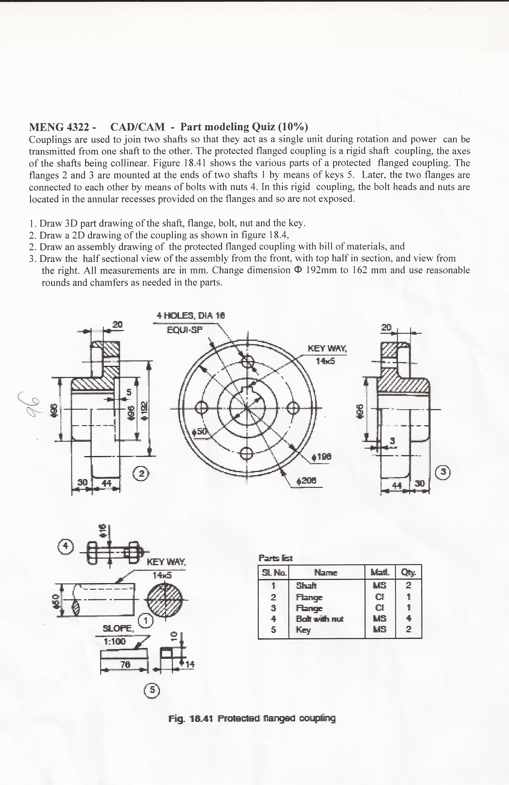
Solved Couplings Are Used To Join Two Shafts So That They Chegg Com

Design Analyse Flange Coupling With Catiav5 Ansys18 Rajeev Nath Skillshare
0 comments
Post a Comment